- 您现在的位置:买卖IC网 > Sheet目录334 > ISL89162FBEBZ (Intersil)IC MOSFET DRIVER 2CH 6A 8SOIC
High Speed, Dual Channel, 6A, 4.5 to 16V OUT , Power
MOSFET Drivers
ISL89160, ISL89161, ISL89162
The ISL89160, ISL89161, and ISL89162 are high-speed, 6A,
dual channel MOSFET drivers. These parts are identical to the
ISL89163, ISL89164, ISL89165 drivers but without the enable
inputs for each channel.
Two input logic thresholds are available: 3.3V (CMOS and TTL
compatible) and 5.0V (CMOS).
Precision thresholds on all logic inputs allow the use of external
RC circuits to generate accurate and stable time delays on both
inputs, INA and INB. This capability is very useful for dead time
control.
At high switching frequencies, these MOSFET drivers use very
little bias current. Separate, non-overlapping drive circuits are
used to drive each CMOS output FET to prevent shoot-thru
currents in the output stage.
The start-up sequence is design to prevent unexpected glitches
when V DD is being turned on or turned off. When V DD < ~1V, an
internal 10k ? resistor between the output and ground helps to
keep the output voltage low. When ~1V < V DD < UV, both outputs
are driven low with very low resistance and the logic inputs are
ignored. This insures that the driven FETs are off. When
V DD > UVLO, and after a short delay, the outputs now respond to
the logic inputs.
Features
? Dual output, 6A peak currents, can be paralleled
? Typical ON-resistance <1 ?
? Specified Miller plateau drive currents
? Very low thermal impedance ( θ JC = 3°C/W)
? Hysteretic input logic levels for 3.3V CMOS, 5V CMOS, and TTL
? Precision threshold inputs for time delays with external RC
components
? 20ns rise and fall time driving a 10nF load.
? NC pins may be connected to ground or VDD to ease PCB
layout difficulties.
Applications
? Synchronous Rectifier (SR) driver
? Switch mode power supplies
? Motor drives, class D amplifiers, UPS, inverters
? Pulse transformer driver
? Clock/line driver
Related Literature
? AN1603 “ISL6752/54EVAL1Z ZVS DC/DC Power Supply with
Synchronous Rectifiers User Guide”
3.5
V DD
3.0
2.5
POSITIVE THRESHOLD
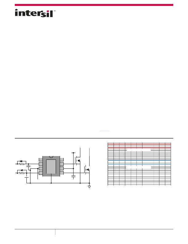
NC
INA
1
2
8
7
NC
OUTA
2.0
GND
INB
3
4
EPAD
6
5
OUTB
1.5
1.0
NEGATIVE THRESHOLD
4.7μF
0.5
0.0
-40
-25
10
5
20
35
50
65
80
95
110 125
TEMPERATURE (°C)
FIGURE 1. TYPICAL APPLICATION
FIGURE 2. TEMPERATURE STABLE LOGIC THRESHOLDS
February 20, 2013
FN7719.3
1
CAUTION: These devices are sensitive to electrostatic discharge; follow proper IC Handling Procedures.
1-888-INTERSIL or 1-888-468-3774 | Copyright Intersil Americas LLC 2010-2013. All Rights Reserved
Intersil (and design) is a trademark owned by Intersil Corporation or one of its subsidiaries.
All other trademarks mentioned are the property of their respective owners.
发布紧急采购,3分钟左右您将得到回复。
相关PDF资料
ISL89165FBECZ
MOSFET DRIVER 2CH 6A 8SOIC
ISL89168FBEAZ
IC MOSFET DRIVER 2CH 6A 8SOIC
ISL89367FRTAZ
IC MOSFET DRIVER 2CH 6A 16TDFN
ISL89401ABZ
IC DRVR H-BRDG 100V 1.25A 8SOIC
ISL89410IBZ-T13
IC DRVR MOSFET DUAL-CH 8-SOIC
ISL9440AEVAL1Z
EVALUATION BOARD FOR ISL9440
ISL9440BEVAL1Z
EVAL BOARD 1 FOR ISL9440B
ISL97631IHTZ-T7
IC LED DRIVR WHITE BCKLGT TSOT-6
相关代理商/技术参数
ISL89162FBEBZ-T
功能描述:IC MOSFET DRIVER 2CH 6A 8SOIC RoHS:是 类别:集成电路 (IC) >> PMIC - MOSFET,电桥驱动器 - 外部开关 系列:- 标准包装:6,000 系列:*
ISL89162FRTAZ
功能描述:IC MOSFET DRIVER 2CH 6A 8TDFN RoHS:是 类别:集成电路 (IC) >> PMIC - MOSFET,电桥驱动器 - 外部开关 系列:- 标准包装:6,000 系列:*
ISL89162FRTAZ-T
功能描述:IC MOSFET DRIVER 2CH 6A 8TDFN RoHS:是 类别:集成电路 (IC) >> PMIC - MOSFET,电桥驱动器 - 外部开关 系列:- 标准包装:6,000 系列:*
ISL89162FRTBZ
功能描述:IC MOSFET DRIVER 2CH 6A 8TDFN RoHS:是 类别:集成电路 (IC) >> PMIC - MOSFET,电桥驱动器 - 外部开关 系列:- 标准包装:6,000 系列:*
ISL89162FRTBZ-T
功能描述:IC MOSFET DRIVER 2CH 6A 8TDFN RoHS:是 类别:集成电路 (IC) >> PMIC - MOSFET,电桥驱动器 - 外部开关 系列:- 标准包装:6,000 系列:*
ISL89163FBEAZ
功能描述:MOSFET DRIVER 2CH 3.3V 6A 8SOIC RoHS:是 类别:集成电路 (IC) >> PMIC - MOSFET,电桥驱动器 - 外部开关 系列:- 标准包装:50 系列:- 配置:高端 输入类型:非反相 延迟时间:200ns 电流 - 峰:250mA 配置数:1 输出数:1 高端电压 - 最大(自引导启动):600V 电源电压:12 V ~ 20 V 工作温度:-40°C ~ 125°C 安装类型:通孔 封装/外壳:8-DIP(0.300",7.62mm) 供应商设备封装:8-DIP 包装:管件 其它名称:*IR2127
ISL89163FBEAZ-T
功能描述:MOSFET DRIVER 2CH 3.3V 6A 8SOIC RoHS:是 类别:集成电路 (IC) >> PMIC - MOSFET,电桥驱动器 - 外部开关 系列:- 标准包装:6,000 系列:*
ISL89163FBEBZ
功能描述:MOSFET DRIVER 2CH 5.0V 6A 8SOIC RoHS:是 类别:集成电路 (IC) >> PMIC - MOSFET,电桥驱动器 - 外部开关 系列:- 标准包装:50 系列:- 配置:高端 输入类型:非反相 延迟时间:200ns 电流 - 峰:250mA 配置数:1 输出数:1 高端电压 - 最大(自引导启动):600V 电源电压:12 V ~ 20 V 工作温度:-40°C ~ 125°C 安装类型:通孔 封装/外壳:8-DIP(0.300",7.62mm) 供应商设备封装:8-DIP 包装:管件 其它名称:*IR2127
